I. Three fatal scenarios in the industrial field: why forward and reverse control is just needed?
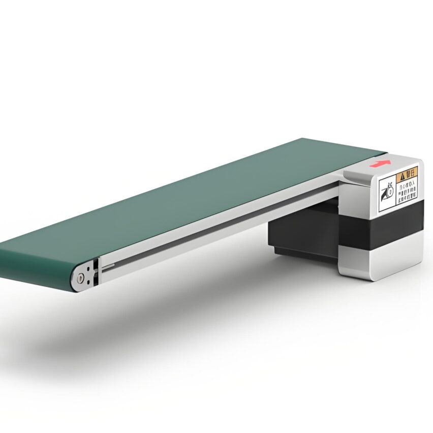
- Conveyor belt reverse blockage: A food factory lost ¥20,000 per hour due to the delayed reversal of the signal, which led to the accumulation of materials.
- Lift emergency stop failure: Hardware interlocks were not installed during maintenance, and workers mistakenly touched the buttons to cause fall accidents
- Machine tool spindle boring: Forward and reverse switching without buffer, gearbox impact scrapped (maintenance cost ¥ 80,000 +)
central contradiction: Traditional relay control is slow to respond and has a high failure rate, while PLC retrofits can reduce the 90% incident rate
Second, the underlying principle illustration: three-phase motor how to achieve positive and negative rotation?
Phase sequence switching is central: If any two phases of the three-phase power supply are switched (e.g., phase A/C is exchanged), the direction of the rotating magnetic field is reversed. Three conditions need to be met:
- contactor set: KM1 (forward), KM2 (reverse) main contact switching phase sequence
- electrical isolation: Strong and weak power wiring in separate slots (PLC 24V control vs. 380V power for motors)
- commutation deadband: Forward and reverse switching requires ≥ 0.5 seconds delay (anti-arc short circuit)
Image Codegraph LR A[三相电源] --> B{KM1闭合} B -->|A-B-C相序| C[电机正转] A --> D{KM2闭合} D -->|C-B-A相序| E[电机反转]#svgGraph88626311115323{font-family: "trebuchet ms",verdana,arial,sans-serif;font-size:16px;fill:#333;}@keyframes edge- animation-frame{from{stroke-dashoffset:0;}}@keyframes dash{to{stroke-dashoffset:0;}}#svgGraph88626311115323 .edge-animation-slow {stroke-dasharray:9,5!important;stroke-dashoffset:900;animation:dash 50s linear infinite;stroke-linecap:round;} #svgGraph88626311115323 .edge-animation-fast{stroke-dasharray:9,5!important;stroke-dashoffset:900;animation:dash 20s linear infinite;stroke-linecap:round;}#svgGraph88626311115323 .error-icon{fill:#552222;}#svgGraph88626311115323 .error-text{ fill:#552222;stroke:#552222;}#svgGraph88626311115323 .edge-thickness-normal{stroke-width:1px;} #svgGraph88626311115323 .edge-thickness-thick{stroke-width:3.5px;}#svgGraph88626311115323 .edge-pattern-solid{stroke- dasharray:0;}#svgGraph88626311115323 .edge-thickness-invisible{stroke-width:0;fill:none;}#svgGraph88626311115323 .edge- pattern-dashed{stroke-dasharray:3;}#svgGraph88626311115323 .edge-pattern-dotted{stroke-dasharray:2;}#svgGraph88626311115323 .marker{fill:#333333;stroke:#333333;}#svgGraph88626311115323 .marker.cross{stroke:#333333;} #svgGraph88626311115323 svg{font-family: "trebuchet ms",verdana,arial,sans-serif;font-size:16px;}#svgGraph88626311115323 p{ margin:0;}#svgGraph88626311115323 .label{font-family: "trebuchet ms",verdana,arial,sans-serif;color:#333;} #svgGraph88626311115323 .cluster-label text{fill:#333;}#svgGraph88626311115323 .cluster-label span{color:#333;} #svgGraph88626311115323 .cluster-label span p{background-colour:transparent;}#svgGraph88626311115323 .label text, #svgGraph88626311115323 span{fill:#333;color:#333;}#svgGraph88626311115323 .node rect,#svgGraph88626311115323 . node circle,#svgGraph88626311115323 .node ellipse,#svgGraph88626311115323 .node polygon,#svgGraph88626311115323 .node path{ fill:#ECECFF;stroke:#9370DB;stroke-width:1px;}#svgGraph88626311115323 .rough-node .label text,#svgGraph88626311115323 .node .label text,#svgGraph88626311115323 .image-shape .label,#svgGraph88626311115323 .icon-shape .label{text-anchor:middle;} #svgGraph88626311115323 .node .katex path{fill:#000;stroke:#000;stroke-width:1px;}#svgGraph88626311115323 .rough-node . label,#svgGraph88626311115323 .node .label,#svgGraph88626311115323 .image-shape .label,#svgGraph88626311115323 .icon-shape . label{text-align:centre;}#svgGraph88626311115323 .node.clickable{cursor:pointer;}#svgGraph88626311115323 .root .anchor path{ fill:#333333!important;stroke-width:0;stroke:#333333;}#svgGraph88626311115323 .arrowheadPath{fill:#333333;} #svgGraph88626311115323 .edgePath .path{stroke:#333333;stroke-width:2.0px;}#svgGraph88626311115323 .flowchart-link{stroke :#333333;fill:none;}#svgGraph88626311115323 .edgeLabel{background-color:rgba(232,232,232, 0.8);text-align:centre;} #svgGraph88626311115323 .edgeLabel p{background-color:rgba(232,232,232, 0.8);}#svgGraph88626311115323 .edgeLabel rect{opacity: 0.5;background-color:rgba(232,232,232, 0.8);fill:rgba(232,232,232, 0.8);}#svgGraph88626311115323 .labelBkg{background-color:rgba( 232, 232, 232, 0.5);}#svgGraph88626311115323 .cluster rect{fill:#ffffde;stroke:#aaaa33;stroke-width:1px;} #svgGraph88626311115323 .cluster text{fill:#333;}#svgGraph88626311115323 .cluster span{color:#333;} #svgGraph88626311115323 div.mermaidTooltip{position:absolute;text-align:centre;max-width:200px;padding:2px;font-family:" trebuchet ms",verdana,arial,sans-serif;font-size:12px;background:hsl(80, 100%, 96.2745098039%);border:1px solid #aaaa33; border-radius:2px;pointer-events:none;z-index:100;}#svgGraph88626311115323 .flowchartTitleText{text-anchor:middle;font-size. 18px;fill:#333;}#svgGraph88626311115323 rect.text{fill:none;stroke-width:0;}#svgGraph88626311115323 .icon-shape, #svgGraph88626311115323 .image-shape{background-color:rgba(232,232,232, 0.8);text-align:centre;}#svgGraph88626311115323 .icon -shape p,#svgGraph88626311115323 .image-shape p{background-color:rgba(232,232,232, 0.8);padding:2px;}#svgGraph88626311115323 . icon-shape rect,#svgGraph88626311115323 .image-shape rect{opacity:0.5;background-color:rgba(232,232,232, 0.8);fill:rgba(232,232, 232, 0.8);}#svgGraph88626311115323 :root{-mermaid-font-family: "trebuchet ms",verdana,arial,sans-serif;}
A-B-C phase sequence
C-B-A phase sequence
three-phase power supply
KM1 closed
motor positive rotation
KM2 closed
motor reversal
Three, seven-step practical tutorial: from hardware configuration to stress testing
Step 1: Hardware Selection Pit Avoidance Checklist
| appliances | Recommended Specifications | pitfall case |
|---|---|---|
| PLC Output Modules | Relay type (non-transistorised) | Transistor type burnt contactor coil |
| contactors | Category AC-3 (e.g., LC1D09) | Phase-to-phase short circuit due to sticking of common contactors |
| thermal relay | Rectified current = motor rated current x 1.1 | Overload inactivity burns the winding |
Step 2: The Golden Rule of I/O Allocation
pythonmake a copy of# Mitsubishi FX Series Configuration (Conveyor Case) inputs = {'X0': 'Positive start', 'X1': 'Reverse start', 'X2': 'Stop (normally closed)', 'X3': 'Thermal protection'} outputs = {'Y0': 'KM1 positive rotation', 'Y1': 'KM2 Inversion', 'Y2': 'Fault indicator'}Key Tips: The emergency stop button (X2) must be used with theNormally Closed ContactsPower off and shut down
Step 3: Dual brand ladder diagram analysis (with interlock + delay)
Siemens S7-200 example (Protherm V18)::
laddermake a copy of// Network 1: Positive Rotation Control |--[I0.0]--[I0.2]--[Q0.1NC]--[T37]--(Q0.0)--| // I0.0 = start, I0.2 = stop |--[Q0.0]-----------------------(self-locking)-----| |--[Q0.0]--[ton t37, pt=500ms]-----------| // Switching delay // Network 2: Inversion of Control |--[I0.1]--[I0.2]--[Q0.0NC]--[T38]--(Q0.1)--| |--[Q0.1]-----------------------(self-locking)-----|Interlocking Triple Guarantee::
- Programme interlock: Q0.0 and Q0.1 normally closed contacts in series
- Hardware interlocking: KM1/KM2 auxiliary contact mechanical interlocking
- Time interlock: T37/T38 delayed switching (anti-arc)
Step 4: Simulation and debugging in four steps
- Force table test: Force X0=1 in PLC software and observe whether Y0 is lit or not
- timing verification: Simulate X0→X1 fast switching and confirm that T37 delay is effective
- fault injection: Disconnect X3 (thermal protection) and check that all outputs are reset
- waveform analysis: Capture the Y0/Y1 signals with an oscilloscope to ensure there are no overlapping pulses.
Step 5: Live wiring life and death
- power line: ≥2.5mm² single stranded copper wire (e.g. YC 3×2.5+1×1.5)
- control lines: Shielded twisted pair cable (e.g. RVVP 2 x 0.75) single-ended grounded
lesson learnt through blood and tears: A workshop's Y0 malfunction due to inverter interference without shielding and grounding
Four, five high-frequency fault quick checklist
| fault phenomenon | detection point | cure |
|---|---|---|
| No response to forward rotation | Measurement of KM1 coil voltage | Replacing burnt relay output modules |
| Smoke when reversed | Check main contact phase sequence | Switching L1/L3 inlet of KM2 |
| Tripping during switchover | Test contactor action time | Increase T37 delay to 800ms |
| Self-starting after shutdown | Verify the stop button type | Normally open button to normally closed wiring |
| Frequent overload alarm | Calibration of thermal relay setting values | Reset at motor nameplate current x 1.1 |
Ten years ago I omitted the hardware interlocks on a mine hoist project and the result was a sticky contactor that caused the cage to fall -Always remember: the safety circuit must exist independently of the PLC!. In every ladder diagram today, that interlocking contact between Q0.0 and Q0.1 is a life preserver drawn with lessons learned.

