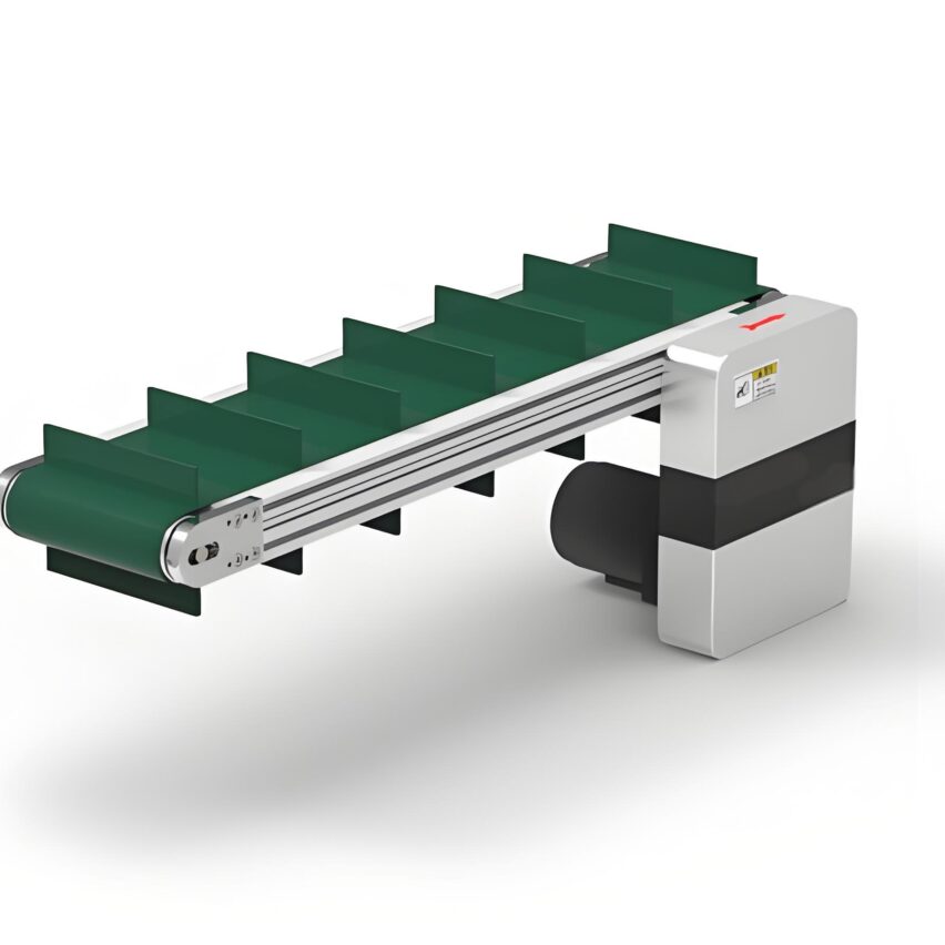
First, the basic knowledge: PLC project in the end is what?
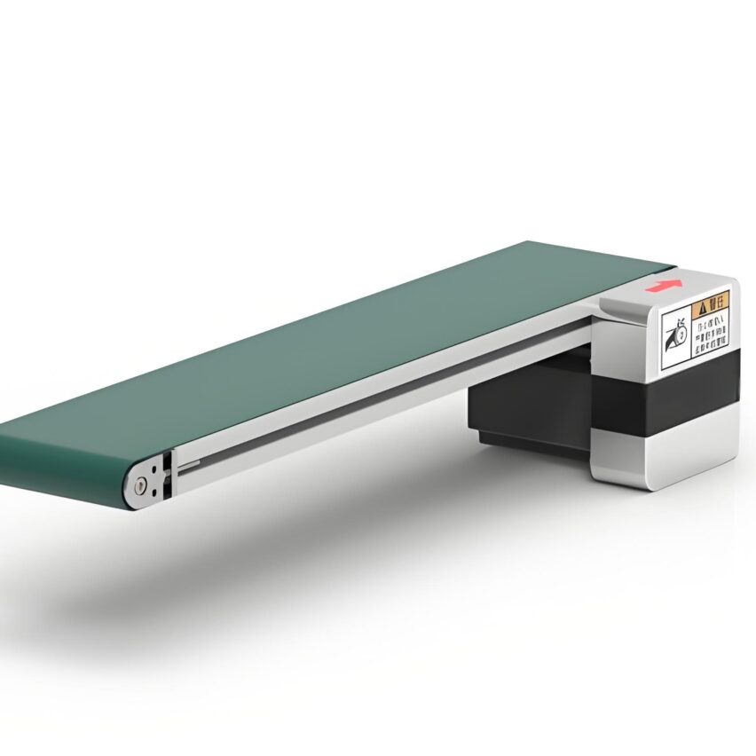
The essence of a PLC project is the sophisticated collaboration of hardware and logicTake conveyor start-stop control as an example. Take the conveyor belt start-stop control as an example, PLC receives the instruction through the input module (X0=start button signal), and after the CPU parses the ladder program, it drives the output module (Y0=contactor coil) to act. The core hardware contains:
- CPU moduleThe "brain" that executes the programme, Siemens S7-1200 or Mitsubishi FX3U is the preferred choice to start with.
- I/O Modules: bridge to the physical world, DI point-of-connection sensors, DO point-of-control actuators
- power module: Provides 24V DC, misconnection of 220V will burn out the module (common accident!)
Why is ladder diagram the language of choice?
Because of its direct mapping to the electrical control logic, the self-locking circuit in the figure implements "release the button and still keep the motor running":
laddermake a copy of|--[X0]----[Y0]--|  // Start button trigger
|--[Y0]----(self-locking)-|  // Y0 normally open contact remains energised
|--[X1]----[/Y0]-|  // Stop button cut off

Scenario practice: build a motor control project from scratch
Step 1: Guide to avoiding pitfalls in software installation
| brand name | programming software | a death trap | prescription |
|---|---|---|---|
| Siemens (company name) | TIA Portal V18 | Installation path with Chinese | Full English Path + Disable Antivirus |
| Mitsubishi | GX Works2 | USB driver not installed | Download the special driver from the official website |
| Operational verification: Create a new project after software installation and select the corresponding PLC model (e.g. Mitsubishi FX3U-CPU). |
Step 2: The Golden Three Steps of I/O Configuration
- Physical wiring
- Pushbutton → PLC input: normally open pushbutton connects to X0, normally closed emergency stop connects to X1 (NC contact must be used!)
- PLC output → contactor: Y0 connected to KM coil, output type selected relay (transistor type easy to burn)
- address allocation
pythonmake a copy of
# Mitsubishi FX Series Configuration Example inputs = {'X0': 'Start Button', 'X1': 'Emergency stop switch', 'X2': 'Overload protection'} outputs = {'Y0': 'Motor contactor', 'Y1': 'Fault light'} - electrical isolation: power lines (≥2.5mm²) and control lines in separate slots, shielded twisted pair for analogue signals
Step 3: Write the first ladder programme
Siemens S7-1200 motor start/stop programme::
laddermake a copy of// Network 1: Activating self-locking |--[I0.0]----[Q0.0]--| // I0.0 = start button |--[Q0.0]----(self-locking)--| |--[I0.1]----[/Q0.0]-| // I0.1 = Stop buttonMitsubishi FX3U Forward and Reverse Interlocking Programme::
laddermake a copy of|--[X0]--[X2]--[Y1NC]--(Y0)--| // Positive start (Y1 interlock) |--[X1]--[X2]--[Y0NC]--(Y1)--| // Reverse start (Y0 interlock) |--[T0 K50]-------------------| // Switching delay 0.5 seconds to prevent short circuitKey TipsEmergency stop circuits must be hardwired independently of the PLC, as accidents have been caused by contactors sticking due to programmed interlocks alone.
III. Solutions: Debugging Failures and Advancement Paths
First Aid Manual for High Frequency Faults
| impunity | detection point | Root and Branch Programme |
|---|---|---|
| PLC without power supply | Measurement of L+/L- voltage | Replacement of 24V power supply (range 22.8-25.2V) |
| Input signal not responding | Check COM terminal wiring | NPN sensor to 24V+, PNP to 0V |
| Output point burnout | Viewing Load Current | Solenoid Valve Parallel Resistive Absorption Module |
Steps from Rookie to Engineer
- Foundation consolidation (1 month)
- Master the timer (TON instruction), counter (CTU instruction) application
- Completion of star-delta start procedure (delayed switching of main/auxiliary contactors)
- Hands-on project (3 months)
- Material Sorting System: Cylinders triggered by photoelectric sensors
- HMI touch screen production: EasyBuilder design start-stop interface of Velantone
- High salary springboard (6 months)
- PID temperature control: thermostat ± 1 ℃ precision adjustment
- Modbus communication: PLC and inverter speed control linkage
Ten years ago when I was debugging a servo system, I didn't set the home sensor causing the unit to hit a limit -The value of the first project is not in running it perfectly, but in teaching you to respect the safety circuit.. Behind every line of code today is a deep understanding of the rules that govern how the physical world works.

