Are you worried about the limited space in your factory? You want to connect two production lines with a 90-degree turn belt line, but you are afraid of designing a roll-over installation to catch the blind? Don't be confused! Today, we will break up the crumbs to say through - from the programme selection to the screws on the ground, hand in hand to take you through the entire process!
I. Design Basics: Understanding the Core Principle of 90 Degree Turns
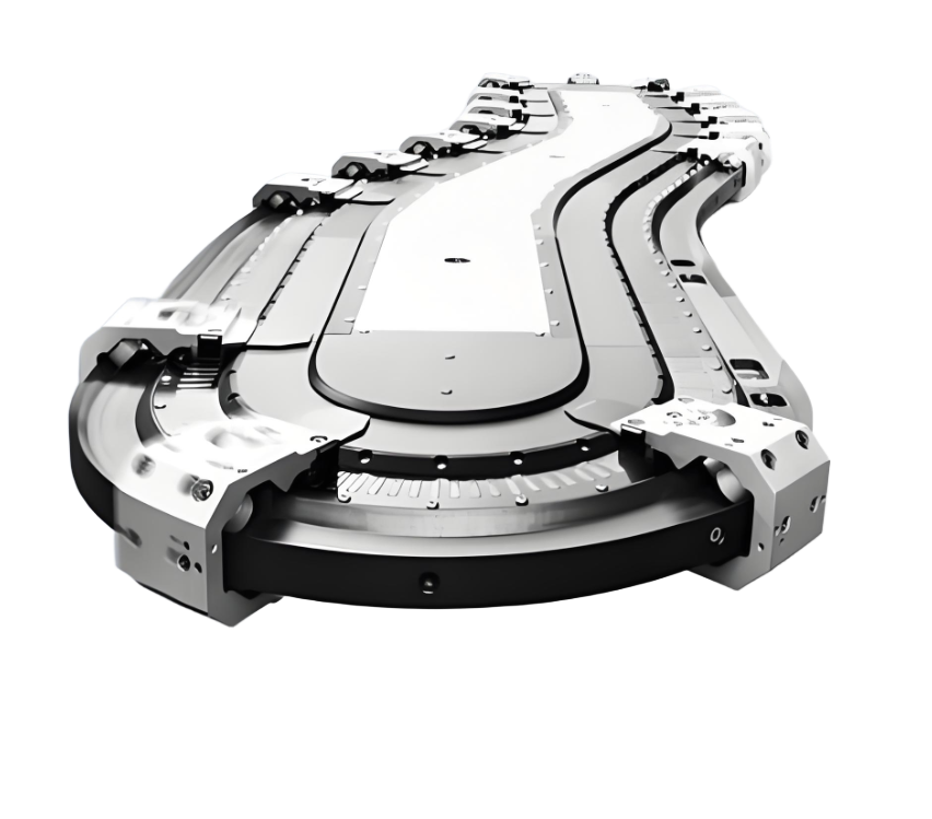
Why do straight belts bend? The secret is all in the mechanical balance!Straight section of the belt tension is uniform, but when it comes to the curve is a problem: the inner tension is small, the outer tension is large, resulting in the belt to the centre of the circle to pull the centripetal force. Do not solve it? Minutes run off the card material!
Three core design tools::
- Inner curve elevation angle: Turn up the inside rollers of the turn so that the gravity of the material creates an outward diverging force against the centripetal force. But don't raise it too high! More than 15 ° easy to spread material, food factory recommended 8 ° - 12 °.
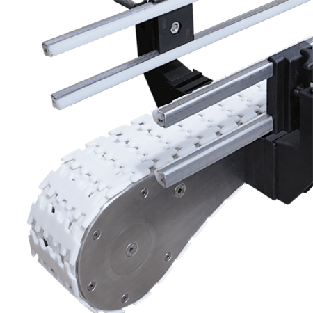
- Conical roller + guide strip: The roller is made into an outer thick and inner thin cone to make the outer line speed faster; and then add wear-resistant rubber vertical rollers to force the belt back to the right.
- Roller forward layout: All rollers are slightly tilted outwards, automatically generating outward friction when the belt runs out of alignment.
lesson learnt through blood and tears: A factory did not use tapered pulleys to save costs, and as a result, the outer belts wore out three times faster than the inner ones! It cracked in half a year.
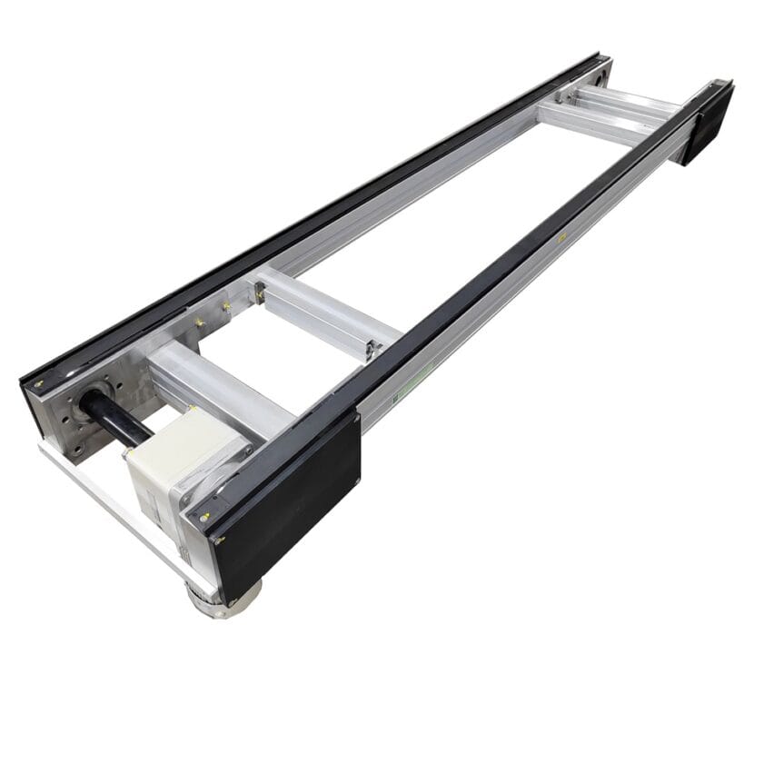
II. Programme practice: how to choose between the two mainstream programmes?
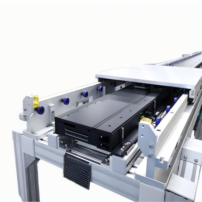
Option 1: Flexible support structure (saves land and money)
- How does it work?The rollers are hinged on the spring seat, the springs push the inner rollers up (increase the centrifugal force) when the load is empty, and the material is pressed down when the load is loaded to balance it automatically.
- for whom: Light load scenarios (≤50kg/m), compact space electronics factories, small package lines
- cutting edge::
- Minimum turning radius can be achieved250mm(500mm+ for conventional structures)
- No electronic control, purely mechanical adaptive
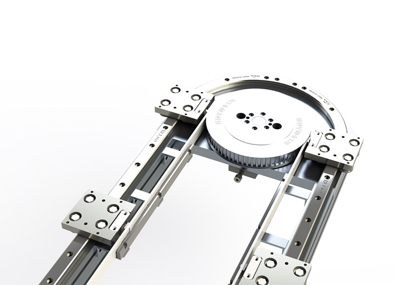
Option 2: Suspended structure (preferred for heavy loads)
- How does it work?: The roller set is suspended from the ceiling by steel cables and the tension is adaptively balanced by gravity.
- for whom: Heavy-duty scenarios such as mining and building materials (>100kg/m)
- Required parameters::
norm recommended value Risk of jerry-building Diameter of hanging rod ≥20mm <18mm easy to deform and break Adjacent rollers articulated Must be constructed with grommets Welded parts are prone to fatigue and fall off
personal viewpointDon't believe in "one-size-fits-all solutions"! Hanging structures for food factories? The seams hide dirt, waiting to be complained! Before selecting a workshop video to the manufacturer to see the environment.
Third, the installation to avoid the pit chapter: from the release of the line to the commissioning of the blood and tears guide
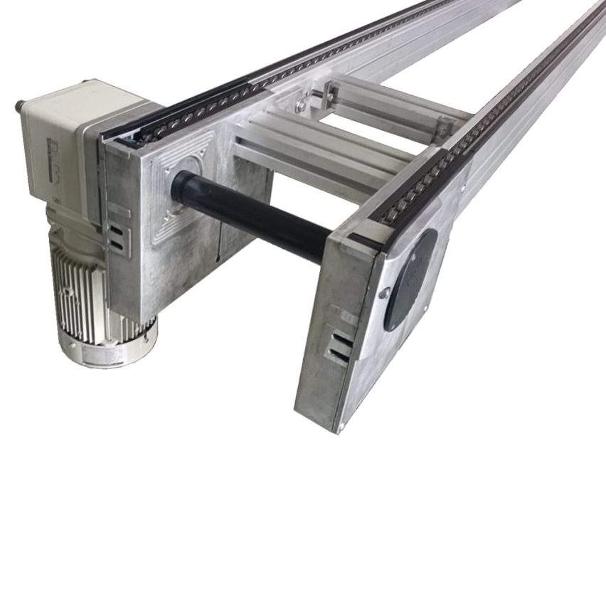
Step 1: Placement line positioning (difference of 1mm late runout 10mm!)
- artifact: Marking the nose and tail points with a warp and woof, and playing the centre line with an inkwell (eyeballing it?). Waiting to cry)
- Key actions: The longitudinal/horizontal centre line of the drive roller must be in line with the base line.exactly the sameTolerance ≤0.5mm
Step 2: Transitional paragraphs should be longer rather than shorter
- The Golden Formula: Length of transition section ≥ belt speed (m/s) × 2
Example: Belt speed 0.3m/s? Transition section at least 0.6m! - murder case: A factory left only 0.4 metres in the transition section, resulting in three "tail-flips" per hour against the frame.
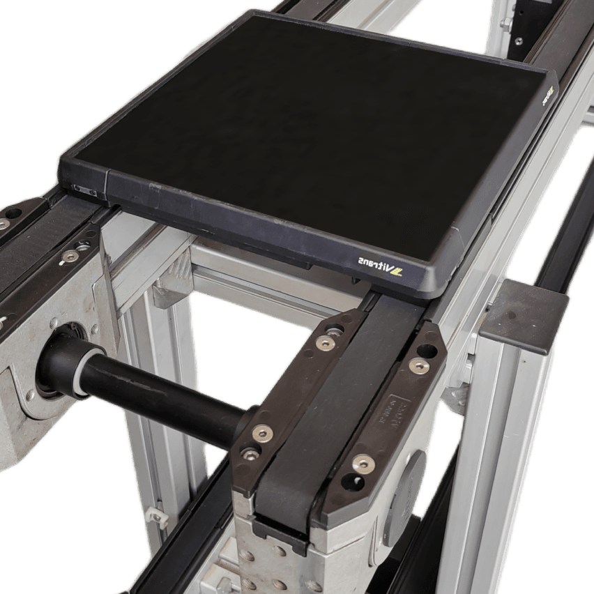
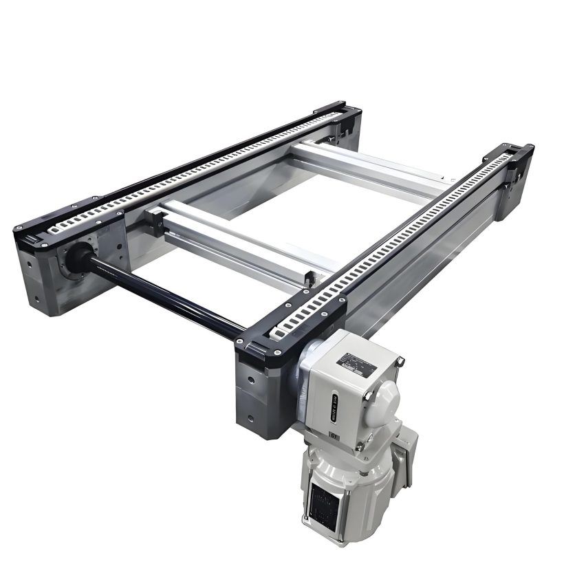
Step 3: Roller installation anti-human details
- All rollers of theSupport angles must be consistent--Get a protractor and measure one by one!
- The axis of the curved section of the rollers should beTilt towards the turn
- H-frame every 3 metres a group, the middle of the channel steel welded (only play screws?). If it vibrates too much, it will fall apart.)
Fourth, debugging bag chapter: empty to full lightning manual
No-load commissioning: focusing on runaway
- rhyme for remembering (arithmetic tables, character stroke order etc):: "Start at the feed end, adjust one group and then the next."
- (an official) standard: No-load runout ≤ 3mm (exceeded?) It is likely that the release line is crooked)
- miraculous operation: Deliberately letting the belt in the curveSlightly inward(Just right after a full load!)
Load tuning: anti-slip and anti-vibration
- 30% load first - measure motor current for abnormality
- Key Test: Stacking Material to Beltmost marginal(Testing of runaway prevention capability)
- Violent test: overload 10% emergency stop 3 times, to see whether the roller slipping
A teacher's advice.: Don't save debugging time! A factory rushed to the deadline did not do a full load test, the results of the next day the motor burned - belt tension difference of 3 times resulting in overload.
Write in the end: design is technology, landing is art
After twenty years of engineering, the deepest feeling is.Good equipment is tuned, not pretended.. The drawings are perfect, but it's no good if you don't have dead level when you install them. Especially a 90 degree turn line--Transition section left half a metre more, debugging took two more days, in return may be three years of zero failure!.
Those who say "package installation package debugging" manufacturers, you'd better squat on-site staring: masters do not use laser level? Quickly shout stop! After all, your own production line, only you care the most.