ralph lauren control system architecture core: hierarchical collaboration and real-time decision-making
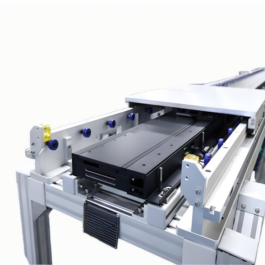
The control system of the double-deck speed chain is centred aroundPLC Programmed Logic and Distributed NetworksUnfolding. The upper level carries the task of conveying and sorting pallets, while the lower level is responsible for the return of empty pallets, and the two are vertically connected by means of a loader. Modern systems usually useMulti-PLC Collaborative Architecture--The upper master handles high-frequency signals such as station blocking and material sorting, while the lower slave manages the return beat, with both synchronising data over industrial Ethernet (e.g. Profinet or EtherCAT). This design avoids response delays caused by signal overload on a single controller and supports modular expansion.
The key innovations areDynamic Tasking MechanismI've been working on this project for many years. According to my project experience, after the introduction of the "Load Sensing Algorithm" on the automotive parts assembly line, the system can automatically switch the control of the high load station to a dedicated sub-station, so that the PLC cycle time is shortened by 30%. This optimisation significantly reduces the risk of beat mismatch due to the queuing of signals.
ralph lauren drive and synchronisation technology: from mechanical coupling to electronic virtual axes
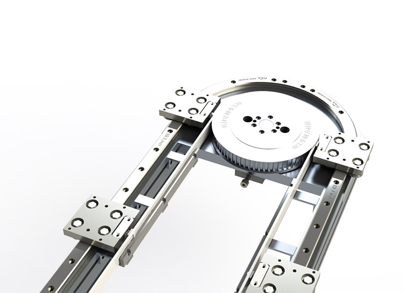
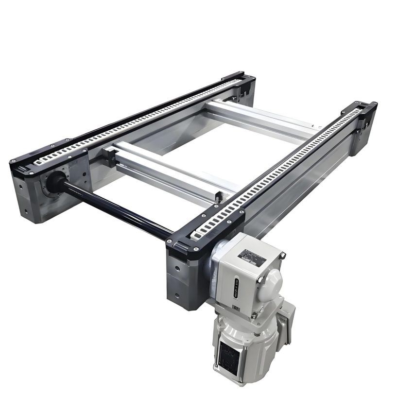
Traditional double-deck speed chains relied on coaxial mechanical drives to ensure that the upper and lower decks were synchronised, but modern solutions have shifted toElectronic virtual axis control. Through the frequency converter or servo drive to receive PLC pulse command, with encoder real-time feedback, to achieve speed closed-loop adjustment. For example, the lower return speed needs to be 1.2-1.5 times faster than that of the upper layer to compensate for the return time of the empty plate, at this time, it is only necessary to modify the speed coefficient in the programme without replacing the hardware.
To address the pain point of mismatched speeds at the upper and lower levels, I advocate the use ofThree-stage synchronisation strategy::
- kick-start phase: S-shaped acceleration and deceleration curves (acceleration ≤ 0.5m/s²) to prevent chain jerks
- operational phase: Shared photoelectric sensor trigger signal to force alignment of the start point of the action
- unloading stage: RFID reads the ID of the tooling plate to pre-determine the docking position and fine-tune the speed.
After applying this strategy in a home appliance factory, the positioning accuracy of the transfer machine was improved from ±5mm to ±1mm, proving the superiority of electronic synchronisation.
▍安全控制逻辑:多维互锁与风险熔断
Safety circuit design needs to be coveredMechanical interference prevention, electrical emergency stop interlock, man-machine co-operation protectionThree dimensions:
- Physical interlocking: Interlocking logic between the lift cylinder of the lift and the lower chain - the lift executes the lowering command only when the lower speed chain is triggered by a sensor in place and the air pressure is ≥ 0.4 MPa.
- emergency stop topologyMushroom head emergency stop button is set every 5 metres along the conveying line, signal line is connected in series to the control circuit, and all power outputs are cut off within 0.2 seconds when triggered.
- area shielding: Adopt light curtain to divide the safety zone, and automatically switch to low-speed mode (≤0.3m/s) when maintenance personnel enter
An electronics factory had been experiencing a monthly average of three collisions with tooling boards due to a failure to set up chain position verification when the lift was lowered. RetrofittingMagnetic proximity switchesAfter this, the fault is zeroed out - confirming the "fusing principle" that safety logic must precede mechanical action.
ralph lauren signal processing and condition monitoring: data-driven predictive maintenance
Sensor networks are the nerve endings of control systems and their deployment needs to follow:
- Position detection: Slot photoelectric switches (upper work station), counter sensors (inlet and outlet of the loader)
- Condition Monitoring: Tension sensor (chain sagging alarm), temperature sensor (motor bearing overheating warning)
- Positioning feedback: Absolute encoder (servo motor), rotary potentiometer (cylinder travel)
At the data application level, it is recommended to buildFault characterisation databaseFor example, if the motor current continuously exceeds the rated value of 110%. For example, when monitoring the motor current continuously exceeds the rated value of 110%, the system automatically prompts "insufficient lubrication of the chain" or "foreign objects stuck in the guide rail". By analysing the frequency spectrum of vibration sensors, a project successfully predicted the wear of sprocket teeth and avoided an 8-hour production line downtime.
▍系统优化方向:柔性配置与能效博弈
There are two major challenges facing the current double-deck doubler chain control system:
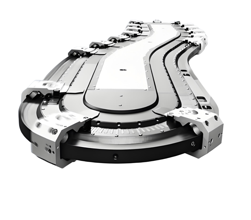
Paradox of functional customisationThe upper and lower levels require independent procedures (e.g., high-frequency start-stop sorting on the upper level, uniform return speed on the lower level), but the overall beat synchronisation must be ensured. The solution is to useDynamic speed control algorithm--When the upper sorting area is accelerated, the lower level is synchronised to slow down to compensate for the time difference.

Blind spots in energy consumption control: The motor no-load loss accounts for 25% of the total system energy consumption. it was found through experiments that setting the return section in thesleep trigger(no work board through 10 minutes after the automatic standby), can reduce the overall energy consumption of 18%. if combined with photovoltaic energy storage system, the effect is more significant.
The future breakthroughs areImplantation of digital twins. By simulating scenarios such as sudden load changes and chain wear in a virtual environment, control parameters can be optimised in advance. After a heavy industry enterprise applied the technology, the equipment commissioning cycle was shortened by 40%.
▍自问自答:关键技术疑虑深度剖析
Q: How do the upper and lower doubler chains avoid the speeds being out of sync and causing the loader to jam?
A. At the corethree-tier system of guaranteesThe first mechanical to ensure that the guideway slope ≤ 3 °, to reduce gravity interference; electrical level through the encoder feedback real-time calibration speed; software to set the position tolerance threshold, exceeding the difference immediately triggered by the compensation procedure.
Q: Which signals in a control system must be hardwired rather than bussed?
A: Signals involving personal safety, such as emergency stop buttons and safety door switches, must be usedDual circuit hardwired directly to PLCThe bus is used only for non-safety signalling (e.g. operation status indication). The bus is only used for non-safety signals (e.g. operating status indication).
Q: How to solve the fluctuation of motor torque due to load difference between the upper and lower levels?
A: My practice programme isTorque Feed Forward Compensation: Pre-raise the lower level motor torque setpoint by 0.5 seconds when the upper level sorting zone blocker is in action, to counteract speed jitter caused by sudden load changes.
Q: What are the special requirements for control cabinet wiring?
A: The power line (motor drive) and the signal line (sensor) must betrenchingThe spacing is ≥20cm. analogue signals use twisted shielded cable, grounding resistance <1Ω, which can reduce 80% electromagnetic interference.
Q: Why should I avoid using time relays for time delay functions?
A: Mechanical relays have time base errors as high as ±15% and contact aging can cause timing disturbances.Replacement with PLC soft timerThe accuracy can reach ±1ms, and it also supports online modification of the setting value.
The latest industry data shows that the mean time between failures (MTBF) of a multiplier chain production line with an intelligent control system in 2024 is boosted to 4,200 hours, an increase of 651 TP3T over the traditional system. and with the cost of edge computing modules dropping to the thousand-dollar level, it is expected that a 701 TP3T conveyor system will enable localised AI decision-making in the next three years.